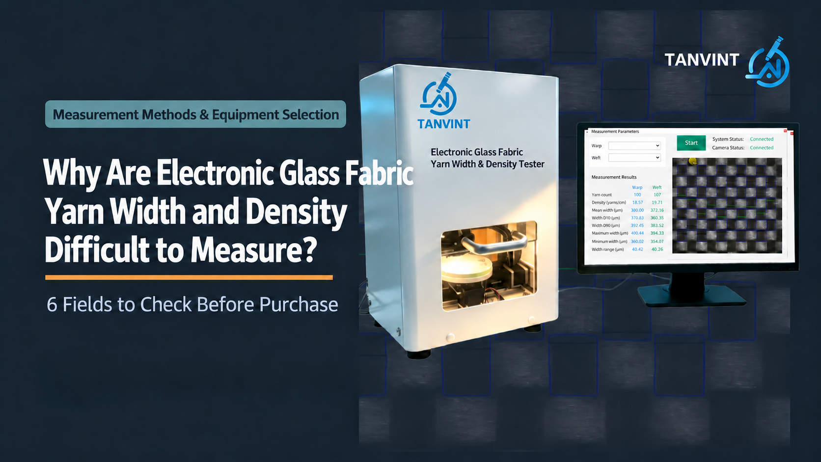
Electronic glass fabric is a base material for copper-clad laminates and printed circuit boards. It is thin and woven from fine yarns; industry designations such as 7628, 2116 and 1080 refer to different yarn counts and thicknesses. Whether inspecting incoming material or finished goods, the essential measurements fall into three groups: warp and weft yarn density, yarn width, and the gaps between yarns. The first group describes how many yarns occur within a given length; the latter two relate to how readily resin can impregnate the fabric. Traditionally, an operator places the fabric under a microscope, counts yarns along a reference line, and manually converts the count into density. The real cost is often less about speed than sample size, consistent measurement rules and record retention: the field of view is limited, results can vary between operators, and the images behind a measurement may not be retained. When a batch dispute arises, the original evidence is unavailable. This article examines these inspection challenges and provides a checklist of fields that can be written directly into procurement documents and technical agreements.
Three Hidden Costs of Reading Measurements Through a Microscope
Manual warp and weft density measurement has established methods, but routine management carries three hidden costs. Limited sampling representativeness: only a few fields of view are usually examined on each specimen, so the counts describe selected local areas. Variations between the selvage and the center of the fabric, or those caused by tension, are difficult to capture statistically. Operator-dependent counting rules: measurement length, direction and the treatment of overlapping yarns depend on individual practice, creating potential differences between teams and between day and night shifts. Limited traceability: once numbers are copied into a spreadsheet, the basis for the judgment remains in the operator's memory. During a customer audit or downstream complaint, the original view cannot be recalled. For electronic glass fabric and copper-clad laminate manufacturers that need batch traceability and customer reports, these three costs deserve as much attention as inspection speed.
Yarn Counts, Yarn Width and Gap Area Are Separate Measurements
Procurement documents often group these three measurements together as density inspection, although they describe different quantities. Warp and weft densities are counts per centimeter or per inch. The conversion rule should be agreed in advance: multiply a value in yarns/10 cm by 0.254 to obtain yarns/inch. For example, 280.95 yarns/10 cm is approximately 71.36 yarns/inch. Changing units does not add or remove yarns, so both the numerical value and its unit label must change together. Yarn width is a dimensional measurement in μm. The mean alone is insufficient; D10, D90 and the range also indicate how uniformly the yarn widths are distributed across the fabric. Gap area describes the open channels between yarns. Gaps that are too small can hinder impregnation and produce dry spots, while gaps that are too large can create resin-rich regions and affect dimensional stability and interfacial reliability after lamination. Yarn width and gap area are measurement fields of the electronic glass fabric model. The woven fabric density tester is intended for warp and weft yarn density. These capabilities should not be assumed to be interchangeable; technical agreements should specify them separately for each model.
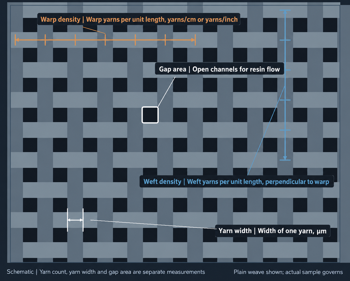
Figure 1 | Schematic illustration. Yarn count, yarn width and gap area are separate measurement fields on the same piece of electronic glass fabric, with different measurement positions and units. A plain weave is shown; the actual sample governs. Figure labels: warp density—warp yarns per unit length, in yarns/cm or yarns/inch; weft density—weft yarns per unit length, perpendicular to the warp-density direction; yarn width—the width of an individual yarn in μm; gap area—the open resin-flow channel between yarns.
Which Specifications Determine Whether a Model Fits Your Application?
The specifications for the TANVINT Electronic Glass Fabric Tester TW-E-LW-N-01 are publicly available and should be checked against the fabric styles you routinely inspect. Its 2× objective and scanning resolution of ≤2.5 μm/pixel determine whether yarn edges can be resolved into countable outlines. The stated measurement precision of 5 μm and the product table's error limit of ≤10 μm are different specifications: software readout increments are not a promise of complete-instrument measurement error. Acceptance should be based on reference specimens and repeated measurements. The yarn-width range is 70–820 μm in each direction, and both warp and weft density ranges are 10–53 yarns/cm. Compare actual measurements from your usual styles with these ranges to determine whether a different objective or scanning setup is needed. A statistical count of 50–265 yarns and a 5 cm × 5 cm scan area indicate that the automated method measures an area of fabric, providing a different sampling scale from a few manually selected microscope views. The specimen size is 6–8 cm, and the manual gives a nominal test time of 30 seconds per test. Actual duration varies with the measurement dimensions and scan area, so production planning should use on-site timing records. Results can be exported to Excel and PDF, with cloud-based management and customized report formats. Shop-floor quality inspectors can operate the system independently after a short period of supervised training.
| Specification | Published value | Question to ask before purchase |
|---|---|---|
| Objective and scanning resolution | 2× objective; resolution ≤2.5 μm/pixel | Can yarn edges be resolved consistently? |
| Measurement precision and error limit | 5 μm / ≤10 μm | How is each specification verified during acceptance? |
| Yarn-width range | 70–820 μm in both warp and weft directions | Does the range cover your thinner and thicker fabric styles? |
| Warp and weft density ranges | 10–53 yarns/cm for both warp and weft | Do the ranges cover the target values of your usual styles? |
| Statistical count and scan area | 50–265 yarns; 5 cm × 5 cm scan area | Does the report represent an area of fabric or a local field of view? |
| Specimen size and test time | 6–8 cm; nominally 30 seconds/test in the manual | Does timing include report generation and measurement in both directions? |
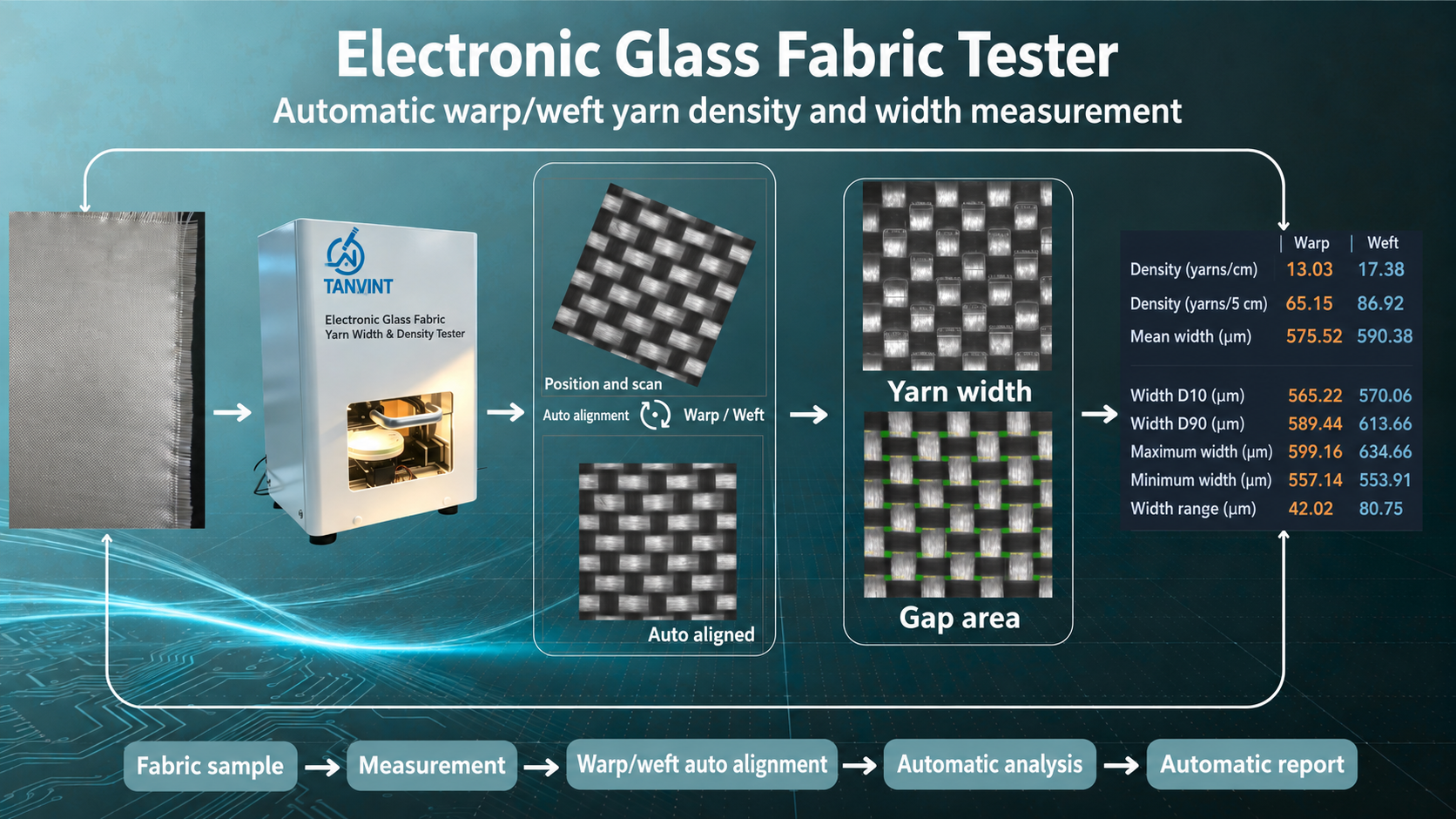
Figure 2 | Workflow and output fields, from specimen placement and automatic warp/weft alignment to automatic report generation.
Testing Your Own Fabric Is More Useful Than Comparing Specification Tables Alone
A step easily omitted during equipment selection is often the one that determines whether acceptance testing can be carried out after delivery. A three-stage validation is recommended. First, submit your own fabric for testing. Check the scanned image for missed or duplicate yarn identification marks, and verify whether the review interface can retain the status of manual corrections in the report. Next, rescan different areas and directions. Compare the mean, D10, D90 and range at different locations within the same batch to determine whether local area selection biases the statistics. If changing the measurement area changes the mean yarn width, those conditions should be recorded as report fields. Finally, produce a template report in the required delivery format. Check that it includes direction, units, measurement area, sample size and retained images, and archive the timing definition together with the on-site records. The website's product pages, article section and Request Sample Testing page provide access to this process. Samples can be submitted for free testing, with a designated engineer coordinating the project and scheduling tests once the fabric arrives.
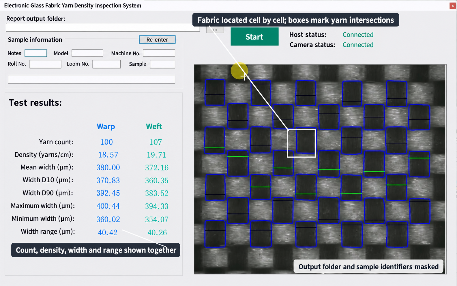
Figure 3 | Electronic glass fabric inspection interface: the fabric is located cell by cell, identification boxes mark the interlacing points, and yarn count, yarn density, yarn width and range are displayed together.
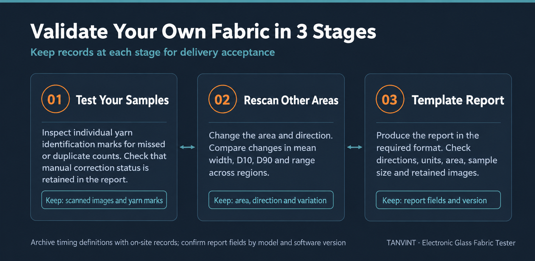
Figure 4 | Three validation stages before delivery acceptance: test your own samples, rescan different areas, and produce a template report. Each stage should leave records that can be compared.
A Checklist to Include in the Technical Agreement
| Field | What the agreement should specify |
|---|---|
| Applicable materials and weave structures | Electronic glass fabric style, yarn count, thickness and usual density range; specimen size of 6–8 cm, square or circular; clamping and flatness conditions confirmed during the on-site demonstration |
| Measured quantities and units | Which of warp density, weft density, yarn width and gap area are required; density fixed in yarns/cm or yarns/inch, yarn width in μm, and the conversion rules included in an appendix |
| Statistical definitions | Scan area, number of yarns counted, how local regions are selected and whether they can be changed; direction and region annotations retained in the report |
| Precision and measurement error | Distinguish software readout increments from complete-instrument measurement error; acceptance based on reference specimens, repeated measurements and comparison with manual results |
| Images and record retention | Whether individual yarn identification images, manual correction status, report versions and specimen identifiers can be retrieved over the long term |
| Timing and capacity | The nominal value stated in the manual, the definition of actual test duration—including report generation and number of directions—and how daily sample volume fits the production schedule |
The fields in this checklist may appear detailed, but they determine whether delivery acceptance becomes a prolonged dispute over measurement rules. During price comparisons, buyers often focus on whether measurement is automatic and how much the equipment costs, leaving statistical definitions, image retention and timing conditions until after delivery. By then, there is usually little room for negotiation. Send this checklist with the request for quotation, ask suppliers to complete it field by field, and then verify each item through tests on your own samples. Equipment selection should deliver more than inspection speed: every report should be reviewable, traceable and acceptable to downstream customers. Separate yarn counts, yarn width and gap area clearly, and agree on validation conditions and record-retention rules in advance to reduce disputes at delivery. TANVINT's product pages and article section provide published specifications, method explanations and frequently asked questions. Readers can follow these links to check the details, or submit sample information and measurement requirements through the Request Sample Testing page so an engineer can respond with the proposed configuration and actual test results.